For any code maintainers out there here are some design ideas on how to do implementation. Each idea is divided into 3 subsections Construction , Installation & Configuration.
Igniter
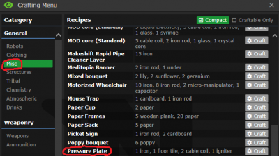
a) Construction: This could be easily implemented in the crafting menu as there is a component already present in the menu which uses all the logical components which could be reused to make the Igniter as well i.e the Pressure Plate

- Pressure plate components which could be reused to make igniter as well
Ideally the code for this could be copied & pasted to then create an Igniter. The materials it requires to create this component logically makes sense as well
We would also need an special type of button just for igniter switch [maybe an igniter button frame] which could be made by holding an single sheet of metal in hand and clicking on it and selecting igniter button frame from the list of menu options presented
b) Installation: To install the igniter we could just simply drop it on a tile and then wrench/unwrench it and now that igniter becomes part of the room/area it is installed in
To install the igniter button we could
->mount it on the wall by clicking on a wall while it is in your hand
->add some wires
->close it with a screwdriver
c) Configuration: To allow the button to find the igniter[or multiple igniters in case player decides to make many of them for a large room] we can use the same logic an air alarm interface uses to find out all vents & scrubbers in the room i.e the once the button is installed the button finds all igniters installed in the current room only . So if you install an igniter in kitchen[for some reason] then the button installed in kitchen would turn on/off all igniters present in kitchen only.
This would be much easier than assigning an unique ID to each igniter and then associating each button with an igniter as this could allow for one switch to toggle multiple igniters
and that marks the end of igniter on to the next one
Air sensor : This gets a little trickier as we also need to discuss atmospheric monitor's in this
a) Construction: The first step would be to create an atmospheric monitor/computer for this we need
->Computer Design[Atmospheric monitor] circuit board which can be printed in circuit board printer
->5 metal sheets to create an computer frame
->wires
->glass
->screwdriver
luckily all these is already present in game so nothing needs to be added/changed .Just stated this for information
To create an air sensor we could either create an air sensor using a RPD[Rapid pipe dispenser] under the device section[the sensor does not have to be color or layer specific] or could be made in an department autolathe/protolathe
b) Installation: Atmospheric computers can be easily installed by reading the wiki page. To install an air sensor we simply click on a tile using the RPD or use an wrench to screw/unscrew the sensor on the floor
c) Configuration: This is divided into 2 sub sections one for the air sensor and one for the monitor
1.0 Configuring the air sensor :
->
Left Click: Upon left clicking an simple log report could be be generated which displays the total moles present on that tile along with their
relative percentages
->
Right Click: Upon right clicking on the sensor while its in hand an simple dialog box could appear which asks the user to enter an name/id for
this sensor. This ID should be compared with the ID of existing air sensors in the station to make sure there is no conflict
2.0 Configuring the atmospheric monotor : Initially when an new monitor is installed it shows up an screen like this

- Newly installed atmospheric monitor
This is a 2 step configuration
->
Link monitor to sensor: the 1st step is to link the monitor to the sensor. This could be done by clicking on the Reconnect button which
would bring down a dialog and would locate all air sensors[by ID] which are present in the current area/room . So if you install an atmospheric monitor
in the kitchen[for some reason] then the reconnect button would find all air sensors installed in kitchen only.
->
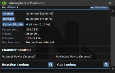
Link monitor to output/input valves: In the picture given below i have linked the monitor to an BZ air sensor[which i spawned using admin tools]
the monitor has no input/output valves

- Connected monitor with no I/O
->
Link Input to monitor: Rather than displaying the text No Input device detected we could instead display an button there saying "Find
Injectors" upon clicking this button we use the same search logic used by the air alarm interface to find all "Injectors"[By ID] installed in the
current area/room. So if you installed the monitor in kitchen this button would find all Injectors in kitchen.
To give an injector an ID we use the same idea as giving an unique ID to the air sensor by right clicking the injector[or some other key combo] or
assign an random 5 character alphanumeric ID to it which is assigned to vents and scrubbers
Upon selecting the injector it gets linked to the monitor
->
Link Output to monitor Rather than displaying the text No output device detected we could instead display an button saying " Find Vents"
upon clicking this button we use the same search logic used by the air alarm interface to find all "Unary Vents"[By ID] installed in the current
area/room. So if you installed the monitor in kitchen this button would find all Unary vents in kitchen.
Every Unary vent by default already has an 5 character alphanumeric code associated with it no problems there
Upon selecting the vent that vent gets linked with the monitor and also SHOULD be disconnected from all air alarm interfaces controlling the
vent so that it can be controlled by the monitor only.
To undo all the configuration we could simply use an multitool on the monitor to reset the monitor to its newly created state
Well these are just ideas i have on how to implement the 2 requested components . Hope this gave someone an technical insight on how this could be done. Really looking forward to seeing this get implemented


